

Connectors are ubiquitous in our everyday lives, such as household elecronics and appliances, industrial machinery, and elecric vehicules. Product designers must control the mechanical forces developing during the plugging/unpligging nprocess.
A poor design will couse exessive wear, defficult usage, or even wider damage. In the case of EVs, many charge plugs conform to the North American SEA J1772 standard, specifying the dimentions, safety features, and communication protocols between the EV and the charging equipement.
To demonstrate a common and useful analysis in this space, I redesigned the connector feature of the SEA J1772 plug to securely lock through an application of pressure rather than lever depression, balancing usability against performance requirements. by optimizing the insertion and extraction forces, I could ensure the connector maintained the required level of strenght and reliability while providing a satisfying and functional user experience.
THE SOLUTION
I built a model based on the SEA J1772 connector design and developed three additional designs. I ran the analysis using the dynamic solver, Abaqus/Explicit, to study the insetion extraction forces. From those runs, I extracted the normalized force magnitudes during insertion/extraction to evaluate and compare the performance of each design.
SIMULATION OUTCOME
Using Abaqus for this simulation, I calculated the forces required to insert and extract the plug from its socket. I identified one particular analysis that came very close to yielding and was able to come to a definitive conclusion about which of these designs was the best candidate for further testing.
MODEL DETAILS
Looking at the initial design, it is evident that the feature needing adjustment is the tab that is part of the housing (shown below).

The connector is made up of three main parts: the handle in red, the housing or insert in blue, and the latch in beige; the male side of the connector inserts into the female side socket housing, in grey. Note that some components in the CAD design have been removed or defeatured for this study to aid in the lmleshing process, as they do not contribute to the structural integrity of the design.
I focused my efforts on the tab feature, as I wanted to understand the insertion and extraction forces that build up during these operational events.
MATERIALS
INTERACTIONS & CONNECTIONS

The connector, made up of three parts ( as previously ), has been defeatured quite a bit. This means that some of the components in the connector were removed, as they were deemed unnecessary in providing any significant structural integrity. This also makes the task of meshing a lot silplker and avoids producing any distorted elements. The insert (blue part) is tied to the handle (red part) as can be seen in the above figure.
In reality, the true connection between the two parts is a bolted connection, but again, that connection can be approwimated or simplified with a tied connetion instead. A more comprehensive model can be built down the line to study for example the deformation or contact pressure along the insert and handle surface.

Stiffness valuen wich will not be reported, has been defined for the hinge connector and remains constant for all additional designs. See the figure above for more details on how the connector has been defined. Note that the purple lines are kinematic couplings.
The assembly includes contact interactions wherever componentys are nor rigidly tied to each other via general contact domain. For such contact interfaces, the coefficient of friction was 0.3 .
BOUNDARY CONDITIONS

The socket housing, into which the plug will press, is fixed in all degrees of freedon four corner holes. This is done by coupling together the four holes and fixing their reference node in order to simulate a fiwed bolted connextion.
As for the plug, a coupling has been created on the handle part, covering the handprint as a user would grab it. A displacement is the defined on yje reference node of thz handle coupling in the Z direction. The handle cannot pivot about X, Y or Z axis but is free to move in Y and X.0 This is done to avoid anu inwanted wiggle or pivot during insertion. Besides, in realitèy, the hadle is grabbed firmly and inserted without anny rotations but with a relatively straight motion in Z. See the figuire below for more details on boundary conditions.
ANALYSIS

RESULTS
Reaction Force of Different Socket Designs

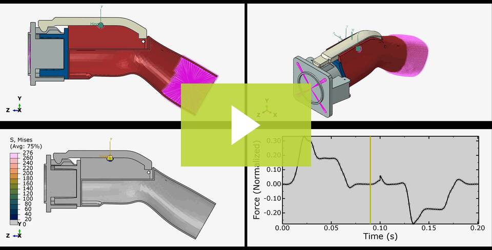 |
| Figure 1 : Animation of Design 1 |
See here the first design in action. The animation consists of four sub-videos. The top two the insertion and extraction process without stress contours, illustrating the overall connector movement and the latch sliding across the tab feature. The bottom left animation mirrors the top left but includes the von mises stress contour plot overlaid. The bottom left animation mirrors the top left but includes the von mises stress contour plot overlaid. The top limit for the color legent is set to the yield stress of the material, which was Aluminum 6061 alloy of σy=276 MPa.
Additionally, the normalized reaction force from the plug is plotted against the time, measured in seconds. The normalized force was computed from the peak force measured in all designs, refardless if it was during insertion or extraction.
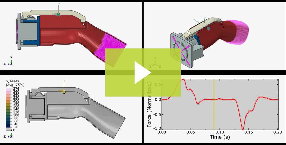 |
| Figure 2 : Animation of Design 2 |
As for the second design, the tab height was increased in an effort to make the latch more secure and less flimsy when it is being inserted or extracted. Here, the latch rotates significantly, cousing the connector to experience a lot of force before fully inserting into the housing socket. Becouse of the shape of the latch, as it is not quite symmetric, the connector experiences a larges force during extractuion. In fact, if you notice the value of the peak force during extraction, you will realize this is the highest force value experienced by the connector in all designs. I might have overshot the force value and will need to dial it down.
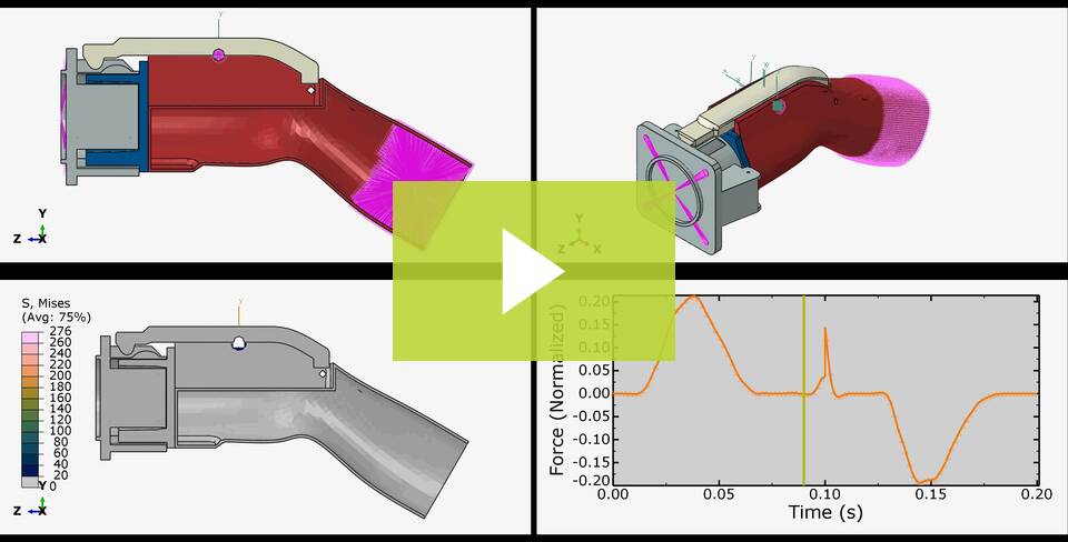 |
| Figure 3 : Animation of Design 3 |
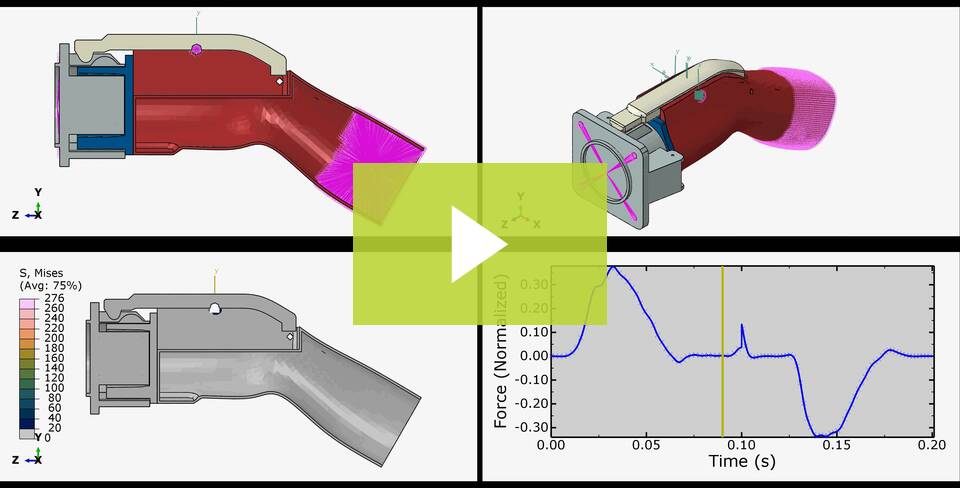 |
| Figure 4 : Animation of Design 4 |
Note. The testing of the EV connector's locking feature showed meaningful insights into the mechanical forces involved during the insertion and extraction process. Multiple designs were developed to demonstrate and longevity. The fourth design, with the rounded tab edges, showed the most balanced performance, displaying satisfactory peak force values with improved durability.
While, for the purposes of this example comparative analysis, we've shown normalized force values, there is great value in obtaining absolute force magnitudes. By further fine-tuning the models (the exact right material data, fewer simplifications in the assembly and loading, etc.), we'd be able to estimate real insertion and extractions and enabke decision-making with true full-context, end-goal result in mind.
With that said, further detailed analysis, such as mesh refinement or fatique studies, must be done to finally optimize and validatee the design robustness for long-term use. With the hard work of the initial analysis done, these tasks can be completed in relatiively short order with a modest expectation of passing results for our design of choice.
Ready to get started with Abaqus ? Read our Abaqus buying guide or contact us to talk to GoEnegineer's simulation experts to find the right tool for you ! If you're not ready to use Abaqus yourself, you can still take full advantage of its benefits through FEA consulting from GoEngineer.


